1. Switches forward packets based on the physical address (such as MAC address) whereas, routers forward packets based on logical address (such as IP address). A frame’s IP address doesn’t change when being forwarded through a switch.
2. The MAC address table of a switch would be empty to begin with. However, it builds the MAC table learning from the frames that arrive at its ports by adding the MAC address and the corresponding port that it had arrived to the MAC table.
3. Cisco switches can be managed out-of-band or In-band. Examples of Out-of-band management are:
Console 0
Auxiliary 0
Examples of in-band management are:
TFTP servers
Network management software like CiscoWorks,
Virtual terminal (vty) ports.
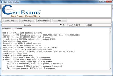
4. The “show version” command on a Catalyst switch displays
The current version of IOS running in a switch
Available hardware, RAM, Flash memory,
Switch uptime
Configuration register’s content
Reason for the last reload etc.
5. Port security enables securing switch ports as required. Typical configuration commands for enabling port security are given below:
Switch#config t
Switch(config)#int fa0/1
Switch(config-if)#switchport port-security
By default, the port is locked to the first MAC address that it learns via the port. You can also manually associate a specific MAC address to a given port by issuing the command:
switchport port-security mac-address {MAC address} in the interface configuration mode.
6. Cisco Visual Switch Manager (CVSM) is software that allows access to Cisco switches over the internet using a web browser, such as Internet Explorer or Netscape Navigator. You can monitor and configure the CVSM compatible switches over the network (remotely). The requirement is that the IP address, gateway and CVSM must be configured on the switch, so that it is accessible over the network using a web browser.
7. The command "no switchport" enables a switch port for layer 3 operation. On the other hand, the command "switchport" enables a switch port for layer 2 operation.
8. To associate a switch with a management VLAN, you need to assign an IP address to the switch. The subnet portion of the switch IP address must match the subnet number of the management VLAN. Note that switches can maintain an IP stack, which enables us to manage the switches either locally, as well as remotely by Telnet.
9. The options available with switchport port security are:
Switchport port-security maximum {max # of MAC addresses allowed}: You can use this option to allow more than the default number of MAC addresses, which is one. For example, if you had a 12-port hub connected to this switch port, you would want to allow 12 MAC addresses, one for each device.
Switchport port-security violation {shutdown | restrict | protect}: This command tells the switch what to do when the number of MAC addresses on the port has exceeded the maximum. The default is to shut down the port. However, you can also choose to alert the network administrator (i.e., restrict) or only allow traffic from the secure port and drop packets from other MAC addresses (i.e., protect).
Switchport port-security mac-address {MAC address}: You can use this option to manually define the MAC address allowed for this port rather than letting the port dynamically determine the MAC address.
10. To telnet to a switch, the following are required:
Assignment of ip address and subnetmask to the management vlan,
Assignment of default gateway IP address.
The following are the typical steps in preparing a switch for telnet access:
Switch(config)#interface vlan <vlan-id>

Switch(config-if)#ip address <ip-address> <subnet-mask>

Switch(config-if)#ip default-gateway <ip-address>

Switch(config-if)#no shutdown
11. The command syntax for assigning a management domain for a switch is:
Switch# vtp domain <domain-name>
For example, if the domain name is newyork, the command is: Switch# vtp domain newyork
You need to create a domain while configuring the first switch in a switch network. For subsequent switches, you only need to join the existing domain. The password is required if the domain need to be secured by a password. The command allows you to create a new domain (in case the first switch is being configured) or to join an existing domain (one or more switches have already been assigned a domain).
12. The enable a switch port for layer 2 functionality use the following commands:
switch(config)#interface <type> <mod>/<num>
switch(config-if)#switchport
The first command enters interface configuration mode for the switch interface <mod>/ <num>, and the second command enables layer 2 functionality on the port.
Use the “no” form of the switchport command to enable layer3 functionality.
13. Switching methods:
Store-and-Forward switching: Here the LAN switch copies the entire frame into its buffers and computes the CRC. The frame is discarded if there are any CRC errors. Giant (more than 1518 bytes0 and Runt (less than 64 bytes) frames are also dropped, if found.
Cut-Through (Real-Time) switching: Here, the LAN switch copies only the destination address into its buffers. It immediately looks up the switching table and starts forwarding the frame. The latency is very less because, the frame is forwarded as soon as the destination address is resolved.
Fragment-Free switching: Here, the switch waits for the collision window before forwarding the entire frame. The collision window is 64 bytes long.
i. Spanning Tree Protocol
1. Spanning Tree Protocol (STP) IEEE Specification 802.1d is used to prevent routing loops. In Cisco Catalyst 5000 series switches, use BDPUs (Bridge Protocol Data Units) to determine the spanning tree topology. STP uses a Tree Algorithm (STA) to prevent loops, resulting in a stable network topology.
2. Following are the possible solutions for preventing routing loops.
Split Horizon - based on the principle that it is not useful to send the information about a route back in the direction from which the information originally came.
Poison Reverse - A router that discovers an inaccessible route sets a table entry consistent state (infinite metric) while the network converges.
Hold-down Timers - Hold down timers prevent regular update messages from reinstating a route that has gone bad. Here, if a route fails, the router waits a certain amount of time before accepting any other routing information about that route.
Triggered Updates - Normally, new routing tables are sent to neighboring routers at regular intervals (IP RIP every 30 sec / and IPX RIP every 60 sec). A triggered update is an update sent immediately in response to some change in the routing table. Triggered updates along with Hold-down timers can be used effectively to counter routing loops.
3. Spanning Tree Protocol (STP) is enabled on every port on Cisco switches, by default. It is preferred to leave it enabled, so that bridging loops don't occur. STP can be disabled selectively on any specific port by issuing the command:
Switch (enable) set spantree disable <mod-number>/<port-number>.

Ex: Switch (enable) set spantree disable 2/4

The above command disables STP on port 4 of module 2.
4. All switches participating in STP exchange information with other switches in the network through messages, known as, Bridge Protocol Data Units (BDPUs). BDPUs are sent out at a frequency of 2 seconds on every port.
5. Internally, STP assigns to each bridge (or switch) port a specific role. The port role defines the behavior of the port from the STP point of view. Based on the port role, the port either sends or receives STP BPDUs and forwards or blocks the data traffic. The different port roles are given below:
Designated: One designated port is elected per link (segment). The designated port is the port closest to the root bridge. This port sends BPDUs on the link (segment) and forwards traffic towards the root bridge. In an STP converged network, each designated port is in the STP forwarding state. The switch with the lowest cost to reach the root, among all switches connected to a segment, becomes a DP (Designated Port) on that switch. If the cost is tied (that is two or more switches have the same cost), the switch with the lowest bridge ID will have the DP (the switch on which DP is elected is called Designated Switch or Designated Bridge). Bridge ID: Priority + MAC address
Root: A bridge can have only one root port. The root port is the port that leads to the root bridge. In an STP converged network, the root port is in the STP forwarding state. All bridges except the root bridge will have a root port.
Alternate: Alternate ports lead to the root bridge, but are not root ports. The alternate ports maintain the STP blocking state.
Backup: This is a special case when two or more ports of the same bridge (switch) are connected together, directly or through shared media. In this case, one port is designated, and the remaining ports block. The role for this port is backup.
6. A switch, participating in Spanning-Tree protocol, passes through the following states:
Blocked state: This is the initial state. All ports are put in a blocked state to prevent bridging loops.
Listen state: This is the second state of switch ports. Here all the ports are put in listen mode. The port can listen to frames but can't send. The period of time that a switch takes to listen is set by "fwd delay".
Learn state: Learn state comes after Listen state. The only difference is that the port can add information that it has learned to its address table. The period of time that a switch takes to learn is set by "fwd delay".
Forward state: A port can send and receive data in this state. Before placing a port in forwarding state, Spanning-Tree Protocol ensures that there are no redundant paths or loops.
Disabled state: This is the state when the switch port is disabled. A switch port may be disabled due to administrative reasons or due to switch specific problems.
7. During the process of Spanning-Tree Protocol execution, Root switch (say, switch A) is elected first. Next, the switch closest to the root switch is selected. This switch is known as Designated switch or Parent switch (say switch B). The frames are forwarded to the root switch(A) through the designated switch(B). Now the lowest cost port on a switch (say switch C) is selected. This is known as the Root port. A Root Port is the port on a switch that has the lowest cost path to the Root Bridge. All Non-Root Switches will have one Root Port. Here, switch B is the designated switch for switch C and switch A is known as the root switch for switch C. Note that switch C is connected to the root switch (A) through its designated switch (B).
8. During the process of Spanning-Tree Algorithm execution, some redundant ports need to be blocked. This is required to avoid bridging loops. To choose which port to use for forwarding frames, and which port to block, the following three components are used by the Spanning-Tree Protocol:
Path Cost: The port with lowest path cost is placed in the forwarding mode. Other ports are placed in blocking mode.
Bridge ID: If the path costs are equal, then the bridge ID is used to determine which port should forward. The port with the lowest Bridge ID is elected to forward, and all other ports are blocked.
Port ID: If the path cost and bridge ID are equal, the Port ID is used to elect the forwarding port. The lowest port ID is chosen to forward. This type of situation may arise when there are parallel links, used for redundancy.
9. When a bridge starts up, the bridge ID is set as root ID. That is, it considers itself as the root bridge. However, while exchanging BDPUs, if it comes across a BDPU that has a bridge ID lower than its own, then the bridge corresponding to the BDPU is considered as root bridge, and this information is propagated. The bridge ID consists of the following:
2-byte priority: The default value on Cisco switches is 0X8000 (32,768), lower the priority, higher the chances of becoming a root bridge.
MAC address: The 6 byte MAC address of the bridge. Lower the MAC address, higher the chances of becoming a root bridge.
Note that, the bridge (or switch) with lowest value of 2-byte priority will become the root bridge. If the priority value is same, then the bridge with lowest value of 6-byte MAC address will become the root bridge.
10. The command "show spantree" includes information about the following:
VLAN number
Root bridge priority, MAC address
Bridge timers (Max Age, Hello Time, Forward Delay)
ii. VLANS
1. The following are the advantages of LAN segmentation using VLANs:
Segmentation of broadcast domains using VLANs result in creation of more bandwidth per user.
Security is provided by isolating users corresponding to different VLANs. Users belonging to one VLAN will not receive frames mean for some other VLAN.
LAN segmentation using VLANs can be done based on job function rather than physical location, if required.
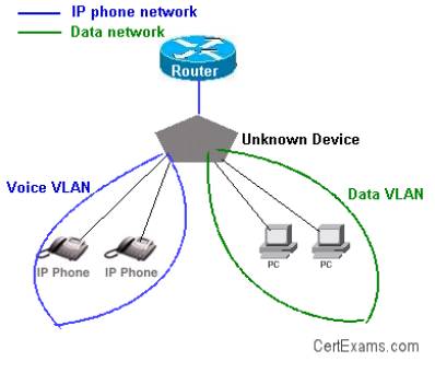
2. VLANs are typically configured on switch ports. However, note that a router is required to switch traffic between VLANs. A switch identifies the VLAN associated with a given frame and forwards the frame to associated ports. Separate VLANs for voice and data traffic improves the privacy and reliability of voice communication.
A single physical port on a router can support one or more VLANs by use of sub-interfaces. There is no need to have as many physical ports on a router as that of VLANs.
3. Inter-VLAN communication can occur only if the router is configured with appropriate sub-interfaces. In this case, there are 4 VLANs (VLANs 100,200,300, and 400), in addition to VLAN 1 (management VLAN). Therefore, 5 sub-interfaces have to be configured on the router interface connecting the switch.
A roll-over cable is required for connecting a terminal to the Console port of a router/switch.
iii. VTP
1. VLAN Transport Protocol (VTP) information can be distributed throughout the network to all stations including servers, routers, and switches.
The VLAN transport protocol are:
ISL: ISL (Inter Switch Link) is the VLAN transport protocol used over Fast Ethernet trunked link.
802.1: 802.1 is the VLAN transport protocol used over FDDI trunked link.
LANE: LAN Emulation (LANE) is the VLAN transport protocol used across an ATM trunked link.
The default VTP configuration parameters for the Catalyst switch are as follows:
VTP domain name: None
VTP mode: Server
VTP password: None
VTP pruning: Disabled
VTP trap: Disabled
2. The VTP domain name can be specified manually or learned across a configured trunk line from a server with a domain name configured. By default, the domain name is not set.
If you configure a VTP password, VTP does not function properly unless you assign the same password to each switch in the domain.
VTP trap is disabled by default. If you enable this feature, it causes an SNMP message to be generated every time a new VTP message is sent.
3. VTP is a Layer 2 messaging protocol. It carries configuration information throughout a single domain. VTP operates in one of three modes:
Server mode: VTP Servers can create, modify, or delete VLANs and other configuration parameters for the specified VLAN domain.
Client mode: A VTP client can't create, change, or delete VLANs.
Transparent mode: A VTP transparent mode is used when a switch is not required to participate in VTP, but only pass the information to other switches. Transparent switches don't work either as Server or clients.
4. Configurations made to a single switch, called VTP server, are propagated across the switch fabric under a single domain control. Other switches, configured as VTP clients, learn the configuration information from the server. Cisco switches such as Catalyst 1900, acting as VTP servers save the VLAN configuration information in their Non volatile memory (NVRAM), whereas clients keep the information only in running configuration.
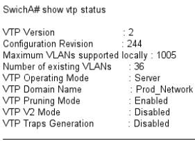
From the output of show vtp status, we can observe that the domain name and the VTP version are different for both the switches. For successfully transferring VLAN information, the version numbers must be same on both the switches. Similarly, the VTP domain name must also be same on both the switches.
5. A VTP advertisement necessarily consists of "Configuration revision number". Every time a VTP server updates its VLAN information, it increments the configuration revision number by one count. VTP clients, use the revision number to enforce the VLAN configuration Update.
6. There are two different VTP versions. VTP version 1 and VTP version 2. These versions are not interoperable. Version 1 is the default version. All switches in a given management domain should be configured in either version 1 or version 2. Some of the advantages of VTP version 2 are as below:
Token Ring support: Supports Token Ring LAN switching and VLANs. If Token Ring is used, this is the version required.
Version number auto propagation: In case that all switches are capable of running Version 2, only one switch need to be Version 2 enabled, Version number is automatically propagated to others.
7. By default, there are no passwords in VTP informational updates, and any switch that has no VTP domain name can join the VTP domain when trunking is enabled. Also any switch that has the same VTP domain name will join and exchange VTP information. This could enable an unwanted switch in your network to manage the VLAN database on each of the switches. To prevent this from occurring, set a VTP password on the switches you want to exchange information.
8. VTP pruning is a technique that enhances the available network bandwidth by reducing the broadcast, multicast, and flooded unicast messages. These frames are not forwarded to network devices that don't have ports associated with a given VLAN. When VTP pruning is enabled, a switch forwards the flooded traffic across a link to another switch, only if that switch has ports associated with that VLAN.
Cert-Ex™ Exam Simulators, Cert-Ex™ Network Simulator, Cert-Ex™ Cheatsheets are written independently by CertExams.com and not affiliated or authorized by respective certification providers. Cert-Ex™ is a trade mark of CertExams.com or entity representing Certexams.com.CCNA™ is a trademark of Cisco® systems