Resources
1. Frame-Relay supports point-point and multipoint connection types. In point-to-point connection type, a single sub interface establishes a PVC connection to another physical interface or sub-interface. In multipoint connection type, a single sub-interface is used to establish multiple PVC connections to several physical interfaces or sub-interfaces. In multipoint Frame-Relay network, split horizon rule is applicable to broadcast traffic. Another important thing to note when configuring Frame-Relay using sub-interfaces: The physical interface on which sub-interfaces are configured would not be assigned any IP address. Even if one is assigned, it should be removed prior to configuring Frame-Relay. Note that if an IP address is assigned to a physical interface, the sub-interfaces defined within the physical interface will not receive any frames.
2. Frame Relay supports two types of virtual circuits (VCs):
1. Permanent Virtual Circuits (PVCs) _ these are permanently established
connection that are used for frequent and consistent data transfers between
DTEs across a Frame Relay cloud.
2. Switched Virtual Circuits (SVCs)
_ these are temporary connections used in situations requiring only occassional
data transfers between DTEs across Frame Relay cloud. The terms "Call Setup",
"Data Transfer", "Idle", and "Call Termination" are associated with SVCs.
Frame Relay SVCs are not widely supported by manufacturers.
3. Frame Relay offers NBMA (Non Broadcast Multi Access) connectivity to various destinations. There might be several PVCs residing on one serial interface. A result of this would be, no broadcasts are forwarded among these PVCs due to implementation of split horizon rule Split horizon rule prevents a route from being advertised onto the same interface (through which the router was learned). One way to allow broadcasts to propagate among these PVCs is to disable split horizon. But, this may again result in routing loops. The recommended solution to this problem is sub-interfaces. Sub-interfaces are logical subdivisions of a physical interface. Routing updates received on one sub interface can be sent to another sub interface. This enables the FR network administrator to implement the split horizon, and at the same time use multiple PVCs on one physical interface.
4. In Frame Relay NBMA networks, if no sub-interfaces are defined, then the routers will not be able to communicate routing information due to split horizon rule. Split horizon is a method of preventing a routing loop in a network. The basic principle is simple: Information about the routing for a particular packet is never sent back in the direction from which it was received. To overcome the split horizon, sub-interfaces can be configured on NBMA networks. A sub interface is a logical way of defining an interface. The same physical interface can be split into multiple logical interfaces, with each sub interface being defined as point-to-point.
5. Given below are salient features of Frame Relay DLCIs:
1. DLCIs (Data Link Connection Identifier) have only local significance
It means, the end devices over FR network can have different DLCI numbers.
2. DLCI number is provided by the FR service provider. DLCI number is mapped
to Layer 3 protocol address using 'frame-relay map' statement.
3. DLCI numbers must be unique on a router.
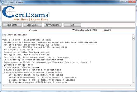
6. The command: show frame-relay pvc 100 displays the traffic statistics for PVC 100. The out put include input packets, output packets, BECN packets, FECN packets, etc.
7. The command frame-relay lmi displays the LMI traffic statistics.
8. The command that displays the current map entries is: show frame-relay map.
9. The command show frame-relay lmi displays the LMI status, where as the command show frame-relay pvc displays the frame-relay pvc status. Show interface displays the physical interface status.
10. The configuration command that statically maps the DLCI with higher
layer protocol is:
Router1(config-if)#frame-relay map <protocol> <protocol-address> <dlci>
[broadcast] [ietf | cisco].
Here, the protocol-address specifies
the destination network protocol address.
For example the following
command maps the IP 192.168.36.9 with dlci 200:
Router1(config-if)#
frame-relay map ip 192.168.36.9 200
Cert-Ex™ Exam Simulators, Cert-Ex™ Network Simulator, Cert-Ex™ Cheatsheets are written independently by CertExams.com and not affiliated or authorized by respective certification providers. Cert-Ex™ is a trade mark of CertExams.com or entity representing Certexams.com.