Resources
NAT (Network Address Translation) can be broadly classified as below:
Static NAT: Static NAT maps an unregistered IP address to registered IP (globally unique) addresses on one-to-one basis. The command used for this purpose is: ip nat inside source static <local-ip> <global-ip>, where, <local-ip> is the local IP address assigned to a host on the inside network. <global-ip> is the globally unique IP address of an inside host as it appears to the outside world.
Dynamic NAT: Maps an unregistered IP address to a registered (globally unique) IP address from a group of registered (globally unique) IP addresses.
Overloading - A special case of dynamic NAT that maps multiple unregistered IP addresses to a single registered (globally unique) IP address by using different port numbers. Dynamic NAT with overloading is also known also as PAT (Port Address Translation).
Overlapping - This occurs when your internal IP addresses belong to global IP address range that belong to another network. In such case, the internal IP addresses need to be hidden from the outside network to prevent duplication. NAT overlapping allows the use of internal global addresses by mapping them to globally unique IP addresses using static or dynamic NAT.
On pinging successfully, you will receive "!" symbol. This symbol is repeated 5 times, as a ping command sends 5 ICMP echo messages to the host.
OSPF determines the router ID using the following criteria:
If no OSPF router ID is explicitly configured, OSPF computes the router-ID based on the items 2, 3, and 4 and restarts OSPF (if the process is enabled and router-ID has changed).
OSPF is a link state technology that uses Dijkstra algorithm to compute routing information. It has the following advantages over Distance Vector protocols such as RIP:
OSPF keeps up to six equal-cost route entries in the routing table for load balancing. Further, OSPF uses Dijkstra algorithm to calculate lowest cost route. The algorithm adds up the total costs between the local router and each destination network. The lowest cost route is always preferred when there are multiple paths to a given destination.
OSPF process identifier is locally significant. Two neighboring router interfaces can have same or different process ids. It is required to identify a unique instance of OSPF database.
Port security enables securing switch ports as required. Typical configuration commands for enabling port security are given below: Switch)# config t Switch(config)# int fa0/1 Switch(config-if)# switchport port-security By default, the port is locked to the first MAC address that it learns via the port. You can also manually associate a specific MAC address to a given port by issuing the command: switchport port-security mac-address {MAC address} in the interface configuration mode.
RIP takes only hop count into account when computing routing entries. Shortest hop count is the winner. Therefore, if RIP is used as routing protocol, a packet will travel from A to B using the 56KBPS link. When both EIGRP and OSPF are configured, EIGRP route takes precedence over OSPF because EIGRP has an administrative distance of 90, whereas OSPF has an administrative distance of 110. Therefore, the route discovered by EIGRP is entered into the routing table. OSPF determines the route by taking only bandwidth into account.
Consider two IPs 172.24.54.0/24 and 172.24.53.0/24. The summarized route is calculated as below:
Step 1:
1. Take the first IP: 172.24.54.0/24 : 172.24. 0 0 1 1 0 1 1 0.0
2. Take the second IP: 172.24.53.0/24 : 172.24. 0 0 1 1 0 1 0 1.0
Note that we are not really concerned about the octets that have equal decimal values. This is because they don’t come into play while calculating summarization route, in this case.
Step 2:
Count the number of bits in the third octet that are aligned (or lined up) with same values. In this case 6 bits are lined up in the third octet. The summarization route is calculated by adding this number (6) to the octets preceding the third (first and second octets). Therefore, the number of bits in the summarized route is 8+8+6 = 22
Step 3:
Calculate the decimal equivalent for third octet with 6 bits as given in the matching binary. That is 0 0 1 1 0 1 x x. Note x is because it corresponds to non matching binary number. It is equal to 128*0 + 64*0 + 32*1 + 16*1 + 8*0 + 4*1 or 32+16+4 or 52.
Therefore, the summarized route is: 172.24.52.0/22
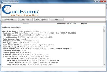
Runts are packets that are smaller than the medium's minimum packet size. For example, Ethernet has a minimum allowed packet size of 64 bytes. Any packet that is less than 64 bytes in size is considered a runt in Ethernet. Giants are packets that bigger than the medium's maximum packet size. Fro example, Ethernet has a maximum allowed packet size of 1,518 bytes. Any packet that is bigger than 1,518 bytes is considered a Giant in Ethernet. CRC error occurs when the check sum calculated at the receiving end of the frame does not match with the check sum calculated at the source end. The most probable reasons for runts, giants, and CRC errors is frame collisions while traveling from source to destination. It is also possible that a network card or device is bad and generating runts and giants.
sh hosts ---> displays the host names and related IP addresses.
sh int s0 ---> Among other things, you can see the encapsulation type (layer 2) used.
Ping ----> sends an ICMP echo message.
Show version: The command displays
a. The current version of IOS running in a switch
b. Available hardware, RAM, Flash memory,
c. Switch uptime
d. Configuration register’s content
e. Reason for the last reload etc.
Show running-config [interface <type> <mod>/<num> | vlan <vlan-id> | module <mod>]: The command displays the contents of the configuration file. Show tech-support: The command is primarily used to send switch information to Cisco TAC support personnel. Verify flash:<filename> -This command is used to verify whether the Flash contents are intact, and not corrupted. The checksum of the flashfile specified is verified for correctness.
Some of the important terms used in Enhanced IGRP are:
SONET defines interface standards at the physical layer of the OSI seven-layer model. The standard defines a hierarchy of interface rates that allow data streams at different rates to be multiplexed. SONET establishes Optical Carrier (OC) levels from 51.8 Mbps (OC-1) to 9.95 Gbps (OC-192).
The High Level Data Link Control protocol (HDLC) is the default encapsulation used on the synchronous serial interfaces of a Cisco router. HDLC is a Data Link layer protocol used to encapsulate and transmit packets over point-to-point links.
STP is enabled on every port on Cisco switches, by default. It is preferred to leave it enabled, so that bridging loops don't occur. STP can be disabled selectively on any specific port by issuing the command: Switch (enable) set spantree disable <mod-number>/<port-number>. Ex: Switch (enable) set spantree disable 2/4 The above command disables STP on port 4 of module 2.
The "hello" packets are sent periodically out of each interface using IP multicast addresses. The hello interval specifies the frequency in seconds that a router sends hellos. This is 10 seconds on multi access networks.
The Catalyst IOS software is very similar to a router IOS. IOS image files are stored in the Flash memory on a switch.
The command traceroute <destination ip address> shows the hop by hop path through the IP network from the source device. The path is shown in terms of IP addresses (Layer 3 addresses) and not MAC addresses (Layer 2 addresses).
The command "show ip ospf database" displays the contents of the topological database maintained by the router. This command also displays router id and the ospf process id.
The command "show spantree" includes information about the following:
The command “no switchport” enables a switch port for layer 3 operation. On the other hand, the command “switchport” enables a switch port for layer 2 operation.
The command show frame-relay lmi displays the LMI status, where as the command show frame-relay pvc displays the frame-relay pvc status. Show interface displays the physical interface status.
The command show ip route displays the contents of the ip routing table. The command show frame-relay map displays the frame-relay mapping information. The commands show frame-relay detail and show map frame-relay are incorrect.
The command syntax for assigning a management domain for a switch is:
Switch# vtp domain <domain-name>
For example, if the domain name is newyork, the command is:
Switch# vtp domain newyork
You need to create a domain while configuring the first switch in a switch network. For subsequent switches, you only need to join the existing domain. The password is required if the domain need to be secured by a password. The command allows you to create a new domain ( in case the first switch is being configured) or to join an existing domain (one or more switches have already been assigned a domain).
The command that is used for configuring OSPF in NBMA mode is: “ip ospf network non-broadcast”. However, note that NBMA mode is used by default.
The configuration command that statically maps the DLCI with higher layer protocol is:
Router1(config-if)# frame-relay map <protocol> <protocol-address> <dlci> [broadcast] [ietf | cisco].
Here, the protocol-address specifies the destination network protocol address.
For example the following command maps the IP 192.168.36.9 with dlci 200:
Router1(config-if)# frame-relay map ip 192.168.36.9 200
The correct syntax for enabling dynamic NAT to translate many inside hosts to an inside global IP address is: ip nat inside source list <access-list-number> pool <pool-name> overload where <access-list-number> is the standard access list number, and <pool-name> is the pool name. Note that the option 'overload' specifies many to one relationship. This configuration is typically used when many hosts with private IP addresses need to access Internet through a specified globally unique IP address.
The default administrative distances are as below:
Directly connected ----- 0
Static Route ------------- 1
EIGRP Summary--------- 5
EIGRP --------------------- 90
IGRP ----------- 100
OSPF ----------- 110
RIP ------------ 120
Unreachable ------------ 255
It is important to remember the default administrative distances for protocols given above because some questions on routing decisions may require this knowledge.
The default administrative distances for important protocols/routes is given below:
a. Connected interface : 0
b. Static route: 1
c. Enhanced Interior Gateway Routing Protocol (EIGRP) summary route: 5
d. Internal EIGRP: 90
e. OSPF: 110
f. Routing Information Protocol (RIP): 120
g. External EIGRP: 170
h. Unknown: 255
The default VTP configuration parameters for the Catalyst switch are as follows:
The VTP domain name can be specified manually or learned across a configured trunk line from a server with a domain name configured. By default, the domain name is not set. If you configure a VTP password, VTP does not function properly unless you assign the same password to each switch in the domain. VTP trap is disabled by default. If you enable this feature, it causes an SNMP message to be generated every time a new VTP message is sent.
The command 'ipconfig' is one of the most widely used commands on a Windows NT/98 computer in a network environment. The commands displays the following details:
The enable a switch port for layer 2 functionality use the following commands:
The first command enters interface configuration mode for the switch interface <mod>/<num>, and the second command enables layer 2 functionality on the port. Use the “no” form of the switchport command to enable layer3 functionality.
The following are main features of route summarization in EIGRP:
Cert-Ex™ Exam Simulators, Cert-Ex™ Network Simulator, Cert-Ex™ Cheatsheets are written independently by CertExams.com and not affiliated or authorized by respective certification providers. Cert-Ex™ is a trade mark of CertExams.com or entity representing Certexams.com.