CCENT (Cisco Certified Entry Network
Technician) Certification Exam Notes
Page1
Page2
Page3
Page4
Page5
Page6
67. Key word: COPY <source> <destination>
This command
copies configuration information to specified location. The following are
some frequently used COPY commands:
- COPY RUNNING-CONFIGURATION STARTUP-CONFIGURATION (alternatively,
you can use an older version of the command, WRITE MEMORY): This command
saves the current configuration to NVRAM.
Alternatively, we can issue
the command using short form:
- COPY RUNNING STARTUP - Copies configuration from RAM to NVRAM
- COPY STARTUP RUNNING - This command merges configuration from NVRAM
to RAM.
- COPY FLASH TFTP - Copies current IOS from router flash memory to
TFTP server.
- COPY TFTP FLASH - Copies image file from TFTP server to flash. This
is used to upgrade the IOS image file to a newer version, or if your
IOS image becomes corrupt.
68. Maximum hop count supported by RIP is 15. A hop count of 16 or greater
is considered unreachable.
69. Network layer is responsible for end to end delivery of packets.
IP and IPX are examples of two routing protocols that work at the Network
layer of the OSI reference model. Network layer addresses remain constant
as a packet travels from source to destination network, whereas physical
(such as MAC address) addresses change with each hop that a packet takes.
For this reason, a Network layer address is a logical address (not hardcoded
like MAC address).
70. Originating source port numbers are dynamically assigned by source
host, usually greater than 1023. The following are the recommended port
numbers:
- Numbers 0 - 255 are used for public applications
- Numbers 255 - 1023 are assigned to companies so that they can use
these port numbers in their applications.
- Numbers above 1023 are used by upper layers to set up sessions with
other hosts and by TCP to use as source and destination addresses.
71. PAP uses 2-way handshaking. Passwords are sent in clear text across
the link. Therefore, PAP is to be used only when it not possible to use
CHAP.
CHAP uses 3-way handshaking. CHAP uses Challenge/ Response method
which provides protection against the password capture while authenticating
the user. One should use CHAP whenever it is possible.
72. PPP and Cisco HDLC support multiple upper layer protocols. SLIP and
LAPB does not support multiple upper layer protocols. PPP supports Password
Authentication Protocol (PAP) and, Challenge Handshake Authentication Protocol
(CHAP).
73. Physical layer is responsible for bit synchronization.
- Repeaters work at Physical layer (Layer 1),
- Bridges and simple switches work at Data Link Layer (Layer 2),
- Routers work at Network Layer (Layer 3) of ISO Reference Model.
74. RIP (and IGRP) always summarizes routing information by major network
numbers. This is called classfull routing.
- RIP and IGRP are examples of routing protocols that use distance
vector. In RIP, the maximum hop count allowed is 15 hops. A hop count
of 16 is considered as unreachable. An RIP router determines the path
to the destination based on the on the amount of hops it takes to reach
the destination. If it had two different ways to reach the destination,
it will simply send the packet via the shortest path (minimum hop count),
regardless of the connection speed. This is commonly known as pinhole
congestion.
- RIP sends its complete routing table out to all active interfaces
at regular intervals (every 30 seconds by default) and when the network
topology changes. RIP routers maintain only the best route (the route
with the lowest metric value) to a destination. After updating its routing
table, the router immediately begins transmitting routing updates to
inform neighbors of the change. These updates are sent independently
of the regularly scheduled updates that RIP routers send. In RIP, update
packets are sent to the immediate neighbors.
75. Router Memory Components:
- ROM (Read Only Memory); Memory containing micro-code for basic functions
to start and maintain the router. ROM is not typically used after the
IOS is loaded. RXBOOT is located here.
- RAM/DRAM : stores the running configuration, routing tables, and
packet buffers. Some routers, such as the 2500 series, run IOS from
Flash, not RAM.
- NVRAM (Non-Volatile Ram): Memory that does not lose information
when power is lost. Stores the system’s configuration file and the configuration
register. NVRAM uses a battery to maintain the data when power is turned
off.
- Flash Memory: Stores the compressed IOS (IOS stands for Cisco Internetwork
Operating System) image. Flash memory is either EEPROM or PCMCIA card.
Flash memory enables you to copy multiple versions of IOS software.
This allows you to load a new lever of the operating system in every
router in your network and then, to upgrade the whole network to that
version at a convenient time.
76. Router modes of operation:
- User EXEC mode:- This is the LOWEST level of access. This allows
examination of router status, see routing tables, and do some diagnostics.
However, you cannot change the router configuration, view the configuration
files, or control the router in any way. The prompt in this mode is "Router>".
- Privileged (enable) EXEC mode:- This mode allows you to have all
the privileges of EXEC (user) mode plus commands that enable you to
view configuration files, change the router configuration, perform troubleshooting
that could potentially disrupt traffic. The default prompt for this
mode is "Router#".
When you are working in the privileged
mode (at # prompt), you can get back to user mode by typing "disable"
at the "#" prompt.
77. Routing protocols job is to maintain routing tables and route packets
appropriately. Examples of routing protocols are RIP, IGRP,EIGRP,OSPF. Routers
can support multiple independent routing protocols and can update and maintain
routing tables for each protocol independently.
Routed protocols are
used to transport user traffic from source node to destination node. Examples
of routed protocols are IP, IPX, AppleTalk.
78. Segments is associated with Transport layer
Packets is associated
with Network Layer and
Frames is associated with Data Link Layer
Ping ----> sends an ICMP echo message.
79. SHOW command is extensively used for seeing the status and configuration
information of the router. Some of the frequently used commands are:
- SHOW RUNNING-CONFIGURATION -This command displays the router's active
configuration file, passwords, system name, and interface settings,
interfaces IP addresses etc.
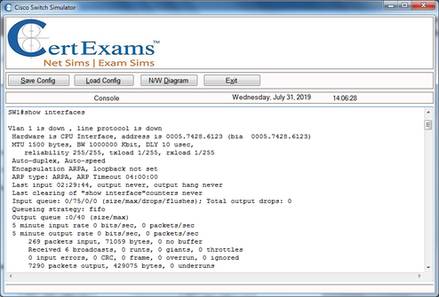
- SHOW INTERFACE - Shows status and configuration information of the
local interfaces. The first line says something like “TokenRing1 is
up, line protocol is up”. The first part “TokenRing1 is up” describes
the physical layer components such as electrical cabling and signaling
are OK. The second part “line protocol is up” means that the router
is detecting keep-alive messages. The router may be put into administratively
down status, at which point the line would read, “TokenRing1 is administratively
down, line protocol is down.”
- SHOW INTERFACE SERIAL 0 - Shows the serial 0 configuration.
- SHOW INTERFACES - Displays statistics for all interfaces configured
on the switch.
- SHOW PROCESS - Displays a router’s CPU utilization.
- SHOW CONFIG - Displays information on the startup configuration.
- SHOW VERSION - Displays information about the system hardware (RAM/ROM),
software version, names of configuration files, and boot-images. This
command will also show the current configuration register value.
- Show IP protocol: This command will show information on RIP timers
including routing update timer (30sec default), hold-down timer (default
180sec). It also displays the number of seconds due for next update
(this is fraction of update timer). This command also gives the network
number for which IP RIP is enabled, Gateway, and the default metric.
Show IP route: This command will display the IP routing table entries.
In addition, it displays the Gateway of last resort (if one is assigned).
It also displays the codes used for various types of routes. Some of
the important codes are:
C: directly connected;
S: Statically
connected
I : IGRP
R : RIP
show IP interface: This command
shows you interface-wise information such as IP address assigned to
each interface, whether the interface is up, MTU etc.
Debug IP RIP:
Debug IP RIP will turn the RIP debugging ON. This will display a continuous
list of routing updates as they are sent and received. This leads to
lot of overhead, which is the reason that you use "undebug ip rip"
to turn-off debugging as soon as you finish with debugging.
- show version: This command displays the current version of the Cisco
IOS. In addition, this command displays the following important information:
- How long the router has been up (length of time since boot-up).
- How the system was started (power on etc.)
- From where the system
was loaded from ( booted via flash , or tftp etc.)
- The contents
of configuration register.
- sh hosts ---> displays the host names and related IP addresses.
- sh int s0 ---> Among other things, you can see the encapsulation
type (layer 2) used.
80. Spanning Tree Protocol (STP) 802.1d is used to prevent routing loops.
In Cisco Catalyst 5000 series switches, use BDPUs (Bridge Protocol Data
Units) to determine the spanning tree topology. STP uses a Tree Algorithm
(STA) to prevent loops, resulting in a stable network topology.
81. Important types of switching used in Cisco devices:
- Store-and-Forward switching: Here the LAN switch copies the entire
frame into its buffers and computes the CRC. The frame is discarded
if there are any CRC errors. Giant ( more than 1518 bytes0 and Runt
(less than 64 bytes) frames are also dropped, if found.
- Cut-Through (Real-Time) switching: Here, the LAN switch copies only
the destination address into its buffers. It immediately looks up the
switching table and starts forwarding the frame. The latency is very
less because, the frame is forwarded as soon as the destination address
is resolved.
- Fragment-Free switching: Here, the switch waits for the collision
window before forwarding the entire frame. The collision window is 64
bytes long.
82. Subnetting:
Subnetting is nothing but creating networks within a network. Subnetting
allows an organization with a single IP address (Class A /ClassB /ClassC)
to have multiple subnetworks, thus allowing several physical networks with
in the organization.
The subnet mask is computed as below:
- Find the Class of the IP address, in this case it is a class B network.
Class B network has the form N.N.H.H. Therefore, we have a total of
16 bits (two octets) for assigning to internal networks and hosts. The
minimum number of host addresses required is 500 (see the question).
The last octet corresponds to 2^8 = 256 hosts which is still less than
500 Hosts.. Therefore, you have to borrow one more bit from the third
octet to make it 256*2 = 512 Hosts. This leaves 7 bits in the third
octet for assigning subnet addresses. This is equal to 2^7=128 subnets.
- Write the 7 bits available for subnetting in third octet in the
form 11111110 (last bit being the Host bit). The decimal equivalent
of the first seven bits is 2^7+2^6+2^5+2^4+2^3+2^2+2^1
= 128 + 64
+32 + 16 + 8 + 4 + 2 = 254.
- Now the subnet mask required is 255.255.254.0.
83. Switches are data link layer devices that enable multiple physical
LAN segments to be interconnected into a single larger network. Two widely
used switching methods are store-and-forward switching and cut-through switching.
84. In store-and-forward switching, an entire frame must be received
before it is forwarded. This means that the latency through the switch is
relative to the frame size—the larger the frame size, the longer the delay
through the switch. Cut-through switching allows the switch to begin forwarding
the frame when enough of the frame is received to make a forwarding decision.
This reduces the latency through the switch. Store-and-forward switching
gives the switch the opportunity to evaluate the frame for errors before
forwarding it. This capability to not forward frames containing errors is
one of the advantages of switches over hubs. Cut-through switching does
not offer this advantage, so the switch might forward frames containing
errors.
85. Switches forward packets based on the physical address (such as MAC
address) whereas, routers forward packets based on logical address (such
as IP address). A frame’s MAC address doesn’t change when being forwarded
through a switch.
86. Switches work at layer 2 of ISO model, which is Data Link Layer.
A switch looks at the destination MAC address before forwarding the frame.
87. TCP and UDP work at transport layer of OSI model or the Host-to-Host
layer of DOD Model. SNMP uses UDP over IP.
Page1
Page2
Page3
Page4
Page5
Page6